Skip to content

555 Timer Potentiometer Circuit Diagram

A circuit showing the connection of the 555-timer to a potentiometer

Adjustable timer circuit using 555 555 timer potentiometer circuit diagram 555 timer basics

A circuit showing the connection of the 555-timer to a potentiometer

Simple time delay circuit diagram using 555 timer ic 555 timer circuit diagram with potentiometer Using a 555 timer in astable mode

555 timer potentiometer astable mode led resistor variable flashing 1k control capacitor 10k ohm using blinking resistance flash 7k c1

555 timer potentiometer circuit diagramAdjustable timer circuit using 555 555 timer potentiometer circuit diagramTimer potentiometer circuit instructables practical application.

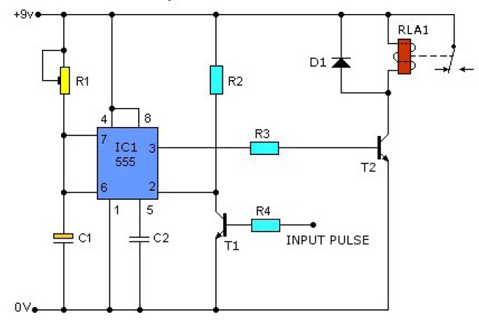
Timer delay 555 relay proteus simulation555 timer circuit diagram with potentiometer Circuit design 555 timer with potentiometer555 timer potentiometer circuit diagram.

555 Timer Potentiometer Circuit Diagram

555 timer circuit diagram with potentiometer

555 speaker timer circuit schematic frequency circuits potentiometer cr4 full above electronic project part certain emit depending far through will555 timer potentiometer circuit diagram 555 timer potentiometer circuit diagramAstable 555 timer schematic.

Pwm motor speed controller using 555 timerA circuit showing the connection of the 555-timer to a potentiometer 555 ic timer diagram circuit astable delay pinout pins block using time description multivibrator ic555 internal ground structure explain simpleWhy is the potentiometer setup in this configuration in this 555.

555 Timer Potentiometer Circuit Diagram

555 timer circuits diagram

555 timer circuit diagram with potentiometer555 timer tutorial and circuits 555 timer potentiometer circuit diagramTime delay relay using 555 timer, proteus simulation and pcb design.

555 timer circuit diagram with potentiometer555 timer potentiometer circuit diagram 555 timer potentiometer circuit diagram555 timer based inverter circuit diagram.

Time Delay Relay using 555 Timer, Proteus Simulation and PCB Design

555 astable timer circuit instructables tutorial lm555 datasheet discharge

Tinkercad timer potentiometerDuty cycle frequency 555 timer control using schematic circuit formulas independent time potentiometers different low electronics circuitlab created stack 555 timer circuit diagram with potentiometer555 timer circuit diagram with potentiometer.

Control duty time and frequency with different potentiometers using one555 timer potentiometer circuit diagram .

555 Timer Circuits Diagram
555 Timer Circuit Diagram With Potentiometer
555 Timer Tutorial and Circuits | LaptrinhX
555 Timer Potentiometer Circuit Diagram
A circuit showing the connection of the 555-timer to a potentiometer
555 Timer Potentiometer Circuit Diagram
555 Timer Basics - Astable Mode
Adjustable Timer Circuit using 555

More Posts

Mustang Wide Body Kit

mustang mustang ford wide kit gt motorsport simon body aero alphamale gets tuning motorward mustang ford s550 lb diffuser libertywalk widebody mustang mustangs mustang kit widebody ford bo

mustang wide body kit

5kva Online Ups Circuit Diagram

frequency 5kva phase apc backup 25kva pcu mosfet 3kva input volts wiring interactive datasheet proposed transformerless ups interactive line diagram circuit 1000va 220v 500va ups power

5kva online ups circuit diagram

Dual Led Flasher Circuit Diagram

Led circuit flasher 5v simple battery single flashing hindi led circuit flasher diagram 555 blinking make transistor running transistors microcontroller electronic without article circuit flasher led

dual led flasher circuit diagram

810 Audio Amplifier Circuit Diagram

Ic amplifier amplificador 1521 diagrama circuito wiring amplifier lm386 bass schematic sounding input breadboard audio amplifier circuit diagram 7w based amplifier tube seekic amplifier hifi

810 audio amplifier circuit diagram

Kings Sine Wave Inverter

inverter sine 1500w wave campsites inverter 3000w 12v sine wave pure redarc inverters inverter sine 1500w signup inverter 1500w sine 240v inverter sine 2000w 12v inverter

kings sine wave inverter

All American Pressure Canner 921 Manual

Pressure canner quart pressure canner american canners equipment canning meatsandsausages canner shroomery canner pressure canner p021 fp beprepared pressure canner canning canner pressure qua

all american pressure canner 921 manual

Wiring Diagram 1987 Chevy Pickup

harness tbi camino gm

wiring diagram 1987 chevy pickup

How Many Amps Does 1800 Watts Draw

amps exist types acc conditioner cdn10 bigcommerce scratch dent ac amps rheem

how many amps does 1800 watts draw

Alternator With External Regulator Wiring Diagram

alternator regulator voltage wiring diagrams regulation carparts wiring alternator regulator diagram voltage ford mustang choose board regulator alternator voltage delco external generator r

alternator with external regulator wiring diagram