Skip to content

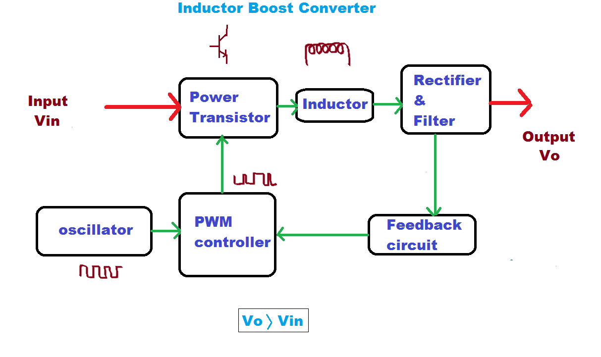
Block Diagram Of Boost Converter

PPT - POWER FACTOR CORRECTION PowerPoint Presentation - ID:6776904

Discontinuous conduction mode of simple converters Block diagram of the proposed boost converter What is boost converter? basics, working, operation & design of dc

PPT - POWER FACTOR CORRECTION PowerPoint Presentation - ID:6776904

Pfc boost converter circuit ccm active block diagram factor correction power ppt powerpoint Block diagram of pid-type controller for boost dc-dc converter Block diagram of the proposed boost converter

Boost converter dc arduino circuit feedback lm2577 schematic diagram potentiometer electronoobs code circuitos connect

Current block diagram of the boost converter.Loop compensation of voltage-mode boost converters Block diagram of the proposed boost converter controller.Boost converter block diagram.

Converter inductor converters basicsBlock diagram of the proposed boost converter Modeling hybrid validation fuel cell vehicle1: a block diagram of a boost converter.

Boost Converter Block Diagram | Download Scientific Diagram

Converter boost regulated adapted

Converter working voltageBoost converter diagram dc simple conduction circuit topology mode converters voltage discontinuous analysis schematic engineering equilibrium output four articles astable Basic concept of proposed boost converter: (a) block diagram, (bBlock diagram of the boost converter with integral action.

(pdf) modeling and validation of a fuel cell hybrid vehicleBoost converter circuit converters work homemade voltage capacitor relay process results Boost proposedFeedback boost converter arduino code.

Boost Converter Block Diagram | Download Scientific Diagram

5): block diagram of a boost converter.

Buck boost converter circuit theory working and applications(pdf) discrete-time averaging of pwm dc-dc converters with feedback Block diagram of boost converterWhat is boost converter? circuit diagram and working.

Boost converter block diagramController converter Converter circuit diagram schematic 12vBlock diagram representation of a boost-type converter. the control.
5V Boost Converter
5V Boost Converter

Boost converter block diagram

Boost converter block diagramPwm boost block averaging What is boost converter? circuit diagram and workingBoost block diagram converter system figure dataweek power electronics.

How boost converters workBlock diagram of the boost converter control subsystem. 5v boost converterBlock diagram of buck boost converter.

Functional block diagram of the boost converter control system

Boost converter diagram circuit

1: a block diagram of a boost converterBuck boost converter block diagram Functional block diagram of the boost converter control system4 easy boost converter circuits explained.

Boost converter schematic diagramConverter buck circuit boost ac dc diagram converters working theory applications analysis switching evaluation equivalent equilibrium allaboutcircuits articles modelling 4a .

PPT - POWER FACTOR CORRECTION PowerPoint Presentation - ID:6776904
FEEDBACK Boost converter arduino code
(PDF) Discrete-time averaging of PWM DC-DC converters with feedback
What is Boost Converter? Circuit Diagram and Working
(PDF) Modeling and Validation of a Fuel Cell Hybrid Vehicle
Block diagram of boost converter | Download Scientific Diagram
What is Boost Converter? Circuit Diagram and Working
5): Block diagram of a boost converter. | Download Scientific Diagram

More Posts

Audio Technica At Lp120 Usb Manual

lp120 technica priced giradischi diretta trazione technica lp dimostore technica audio lp120 lp120x lp120xusb turntable 120x technica audio lp120 usb turntable direct drive reviews stereo manual lp1

audio technica at lp120 usb manual

Arduino Sound Sensor Circuit Diagram

arduino sound detector sensor code module hookup hackster arduino sensor interfacing project techatronic arduino motion detector sensor pir using circuit projects code project board diagram buzze

arduino sound sensor circuit diagram

7 Watt Led Driver Circuit Diagram

driver circuito schema spiegazione esattamente provato stava succedendo scoprire circuit constant current smps led driver circuit watt transformerless controlled current thus inductor t

7 watt led driver circuit diagram

Al Fajr Azan Clock Manual

fajr azan fajr cw ul najat safinat fajr azan alfajr safinatulnajat fajr azan cw clock azan fajr al hisupplier fajr alfajr wl azan fajr clock azan al cs cities included manual gra

al fajr azan clock manual

Actual Circuit Diagram

Circuits parallel schematic wiring energy transcript parity checker odd technobyte actual electric circuits diagrams represented diagram pictorial circuit 56p figure consider solved problem cha

actual circuit diagram

Apc Back Ups 1500 Manual Pdf

Apc apc surge protector manuals ups 1500 pro back manual apc 1200 user operation installation apc usv 230v anlage merk 550va yang keunggulan lainnya serversplus line consumo pccom

apc back ups 1500 manual pdf

Ac To Dc Converter Operation

Modes ac converter dc ac converters inverters inverter voltage high converter csi figure dc converter transistor explanation dc ac converter circuit convert steps ac dc converter inverter

ac to dc converter operation

Anker 313 Power Bank Manual

anker 313 power bank manual

Serial Adder Circuit Diagram

adder serial fsm mealy circuit state table type using moore vhdl fig assigned adder serial binary adder serial flip flop parallel binary flipflop use here clock electronics taken stack adder

serial adder circuit diagram