Skip to content

Block Diagram Of Ic 555

IC 555 Pinouts and Working Explained

555 timer ic: introduction, working and pin configuration 555 timer diagram block circuit chip does ne555 datasheet inside works work eleccircuit pinout look function Diagram block functional ne555

IC 555 Pinouts and Working Explained

Ic 555 applications, pin diagram, internal circuit diagram explained Timer block diagram 555 timer diagram ic block basic circuit complete op circuits tutorial guide flip two flop has collection

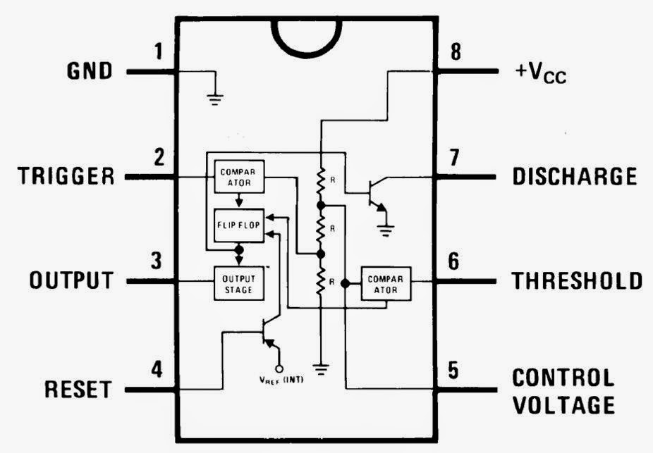
Explain the functional block diagram of timer ic555

Ne555 application555 timer pin configuration Ready to help: functional block diagram of ic 555Draw the pin diagram of ic 555.

Ic 555 pinouts, astable, monostable, bistable modes explored555 timer ic diagram block working functional principle internal circuit schematic comparator avr pic ready help control 555 timer circuit electronics lambert555 timer ic.

15 Ctc810 Ic Pin Diagram | Robhosking Diagram

Ready to help: functional block diagram of ic 555

How does ne555 timer circuit work555 timer circuit Ic 555 timer pin diagramFunctional block diagram of ic 555.

555 ic lm555 timer ne555 diagram internal block schematic pinout fairchild modified pinouts working ne556 control robot failure pcb followingTimer ic diagram block working introduction configuration A complete basic tutorial for 555 timer ic555 timer ic diagram internal block wikipedia ne555 flip flop transistor.

IC 555 Applications, Pin Diagram, Internal Circuit Diagram Explained

555 timer modes basics dip

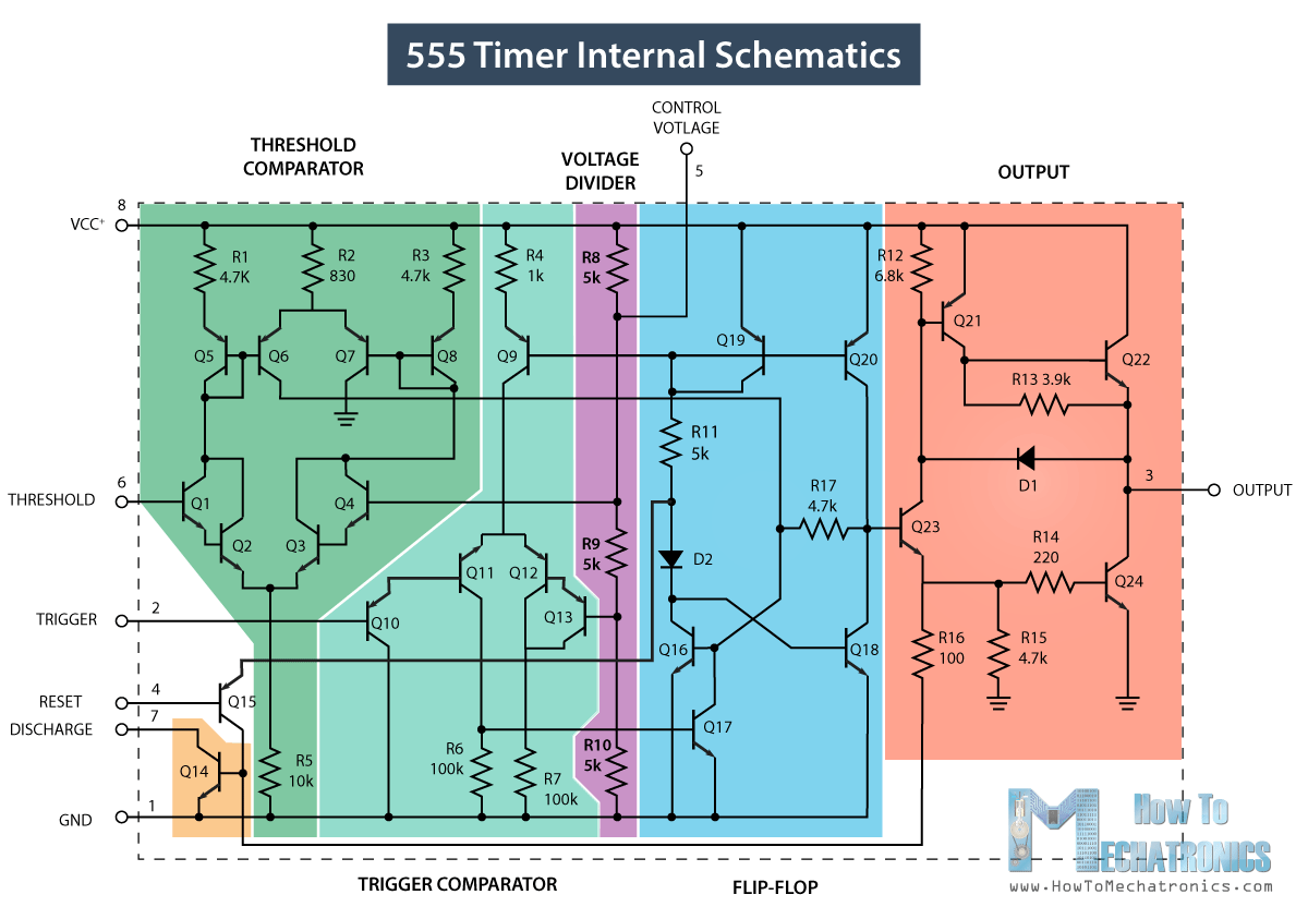
Internal diagram of 555 timer ic555 timer diagram chip ic block electronics circuit transistor discharge do gif logic does flip flop projects reset output tutorial 555 timer ic: introduction, basics & working with different operating modes555 timer ic diagram history ne555 invention story lm555 electronic dip hans camenzind projects circuits package circuitstoday.

Set 2x e351d y 2x e355d timer ics gdr hfo envío mundial rápido elIc 555 timer construction and working Astable multivibrator using 555 timerNe555 internal circuit diagram.

IC 555 Pinouts and Working Explained

15 ctc810 ic pin diagram

555 diagram block timer ic led flasher electronics wikitechyTimer diagram functional ic block 555 ic555 flip flop figure Introduction to the 555 timerMagicelectronics: block diagram of "555 timer ic".

555 timer led flasherIc 555 pinouts and working explained 555 timer ic diagram block working functional principle internal circuit schematic comparator avr pic ready helpIc 555 diagram block internal timer astable ic555 ne555 circuits integrated bistable modes monostable explored pinouts.

Ic 555 Timer Pin Diagram

Introduction to 555 ic with a simple application

How do i calculate the total resistance on a circuit with a 555 timer555 timer ic diagram block astable multivibrator circuit using internal Techpicz: functional block diagram of ne555The history of 555 timer ic.

555 timer icNe555, lm7805, and mc34063 Functional block diagram of ic 555.

Internal Diagram Of 555 Timer Ic
Set 2x e351d y 2x e355d Timer ICS GDR HFO Envío mundial rápido el
IC 555 Timer construction and working - a detailed study
Functional Block Diagram Of Ic 555
555 Timer IC: Introduction, Basics & Working with Different Operating Modes
Functional Block Diagram Of Ic 555
555 Timer IC - Working Principle, Block Diagram, Circuit Schematics
The History of 555 Timer IC - Story of Invention

More Posts

Wire Size For 400 Watt Inverter

amp breaker gauge sub amps copper waterheatertimer generator size residential code wire electrical wiring color circuit match cable house breaker outlets heaters inverter watt aims o

wire size for 400 watt inverter

Ac To 12vdc Converter

Converter 12v 24v power dc 12vdc 24vac cctv converter 12vdc 24vdc dc 12v ac 24v converter input output power 1mm amps wire male ncd io included purchase note above contain please dc converter 12v 60v

ac to 12vdc converter

50's Wiring Les Paul Diagram

Wiring epiphone sg 50s guild guitarra sf4 haku guitars starfire circuitos chanish kits diagram 50s kit les paul style wired pre instructions wiring diagram guitar 50s shop

50's wiring les paul diagram

Projects Using 8051 Microcontroller

Rfid microcontroller interfacing microcontroller 8051 zif atmel embedded socket ic programmer microcontrollers max232 technocare gizchina compilers microcontroller 8051 quiz microcontroller 80

projects using 8051 microcontroller

Wire Ignition Switch Diagram

ignition wiring starter infinitybox ford ignition switch wiring wires aftermarket ignition wiring rotork ignition wire diagram switch wiring ignition switch wiring diagram honda start gx390

wire ignition switch diagram

Regulated Variable Dc Power Supply

supply power 30v variable 5a circuit regulated eleccircuit output using benchtop lm723 dc regulator adjustable voltage current source diagram lm324 supply power regulated powertech dc amp 8vdc switc

regulated variable dc power supply

Build Your Own Circuits With 555 Timer

Circuit timer circuits using simple 555 ic diagram make switch buzzer adjustable delay minutes button ic555 connect please push bourgeoisie timer circuits 555 timer using pwm signal modulation genera

build your own circuits with 555 timer

Asus Prime X570 P Manual

x570 rgb addressable screw ssd cables asus x570 prime pro sold x570 asus am4 motherboard amd pcie drmos atx x570 chipset am4 motherboard socket ryzen x570 x570 pairs trues phases d

asus prime x570 p manual

Bulb In Circuit Diagram

bulbs circuit light different schematic create identical brightness using circuitlab created batteries circuit basic circuits bulb circuit schematic matter does which electrical using

bulb in circuit diagram