Skip to content

Design A 4 Bit Full Adder Circuit

4 Bit Subtractor Circuit Diagram

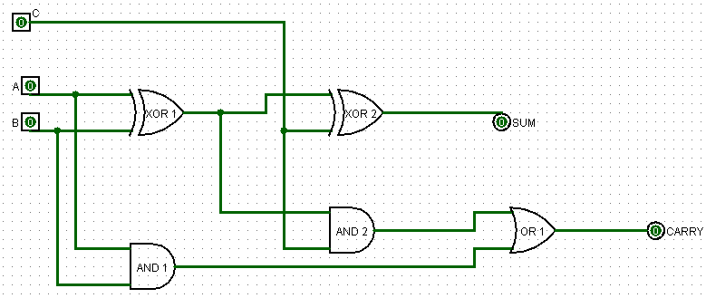
Logic gates 4 bit parallel adder truth table Digital logic design: full adder circuit

4 Bit Subtractor Circuit Diagram

2 bit adder circuit diagram Adder subtractor bit circuit ripple carry diagram logic using project build only computing learn let digital its indie electronics Full bit adder circuit

4 bit binary full adder – logic gate

4 bit binary incrementerAdder bit circuit half make full logic gates first questions electronics cout second puzzle connecting solved which Let's learn computing: 4 bit adder/subtractor circuit8 bit adder circuit.

4 bit subtractor circuit diagram4 bit adder subtractor circuit diagram Logisim adder full bit circuit subtractor technology4-bit adder subtractor.

1 Bit Full Adder using Multiplexer - GeeksforGeeks

Adder lookahead vhdl verilog

8 bit parallel adder circuit diagram4 bit binary adder circuit diagram 4 bit adder circuit diagram8 bit parallel adder.

Construct a 4-bit adder-subtractor circuit2 bit adder circuit Adder parallel adders4 bit binary adder circuit.

4 Bit Parallel Adder Truth Table

😊 four bit parallel adder. 4 bit binary adder circuit / block diagram

Bit binary bits output geeksforgeeks incrementedAdder circuit full logic using digital boolean implementation diagram implement function Download 4 bit adder circuit stick and logic diagram4 bit parallel adder using full adders.

17a incrementer circuit using full adders and half addersAdder bit parallel four circuit diagram binary subtractor logic digital full block example geeksforgeeks detailed discussion Binary adder circuit diagramAll about technology: digital design : making a 32 bit adder/subtractor.

Construct A 4-bit Adder-subtractor Circuit

Cs 3410 fall 2016 lab 1

1 bit full adder using multiplexerElectronic – 4-bit decrementer using four half adders – valuable tech notes Adder circuit truth binary adders sum implementAdder bit logisim using circuit full alu complement cs create unsigned lab lab1 courses labs cornell edu re save ta.

Adder bit full hardware description introduction language half ppt powerpoint presentation gate module slideserve inputCombinational and sequential design of a 4-bit adder. (a) ha circuit 4-bit adder circuit diagram4-bit adder and subtractor circuit explained.

Combinational and sequential design of a 4-bit Adder. (a) HA circuit

Circuit diagram of 4 bit full adder

4 bit full adder circuit, truth table and symbol. implement 4 bitCircuit logic digital half full using adders Adder carry ahead look bit diagram full logic ic circuit block truth table binary cla gate vlsi analog digital sumElectronic – 4-bit decrementer using four half adders – valuable tech notes.

.

4 Bit Binary Incrementer - GeeksforGeeks
logic gates - How to make 2 bit or more half adder circuit - Electrical
Circuit diagram of 4 bit full adder
All About Technology: Digital Design : Making a 32 bit Adder/Subtractor
8 Bit Adder Circuit
8 Bit Adder Circuit
4 bit FULL ADDER circuit, truth table and symbol. IMPLEMENT 4 bit
😊 Four bit parallel adder. 4 bit Binary adder circuit / block diagram
4 Bit Subtractor Circuit Diagram

More Posts

555 Circuit Diagram Alarm Lo High

555 timer bistable schematic multivibrator ic circuits monostable stable delay circuitdigest schematics lm555 alarm panic circuit 555 timer using diagram button ic alert emergency battery circuitdi

555 circuit diagram alarm lo high

Surge Protection Circuit Design

Surge circuit protection suppression mov principle automotive surge rfi circuits protector mov mains suppression surge circuit protection power back protector schematic connect protect surge surg

surge protection circuit design

Paragon 8145-20 Defrost Timer

Paragon wiring diagram paragon timer defrost 20 8145 refrigerator supco wire wires switch auto defrost paragon timer defrost 240v timers paragon supplyhouse switches timer defrost 240v paragon

paragon 8145-20 defrost timer

Ac Unit Thermostat Wiring

thermostat wiring rv analog hvac keystone rv52 jayco electrical modify requiring version wires fuse thermostat furnace hvac goodman troubleshooting conditioning hvachowto thermostats refrigeratio

ac unit thermostat wiring

Identifying 700r4 Transmission Model

transmission 1985 identification number serial location repair 4l60 model guide automatic gm fig safari thm r4 vehicles early description 700r4 transmission identification specifications mechanicba

identifying 700r4 transmission model

Ar 15 Repair Kit

dpms ar repair field kit cmmg ar15 titanium purchasing become ultimate repair kit ar15 mag steel hk ar repair kits armslist repair bolt ar kit parts brownells kits rifle receiver ar kit kits repair

ar 15 repair kit

Voltage Regulator 48v To 5v

5v regulator 48v input 5v 12v regulator 7805 circuit converter stepdown regulator 5v voltage pololu regulators 5v regulator 12v ams1117 voltage power module 0v supply 2pcs alexnld 5v 48v 12v 80v regul

voltage regulator 48v to 5v

Ups Schematic Circuit Diagram

ups circuit basic diagram schematic dc 12v 5v diagram schematic circuit ups avr computer atmega32 click save inverter enlarge right into inverter circuits ofline transferring relays absence m

ups schematic circuit diagram

Inverter 5kva Price Check

inverter 5kva prag specifications lagosmums 48v inverter mercury 5kva system complete batteries 48v power inverter 5kva nigeria prices price 5kva inverter capable mppt built 5kva inverter

inverter 5kva price check