Skip to content

Internal Block Diagram Of Ic 555

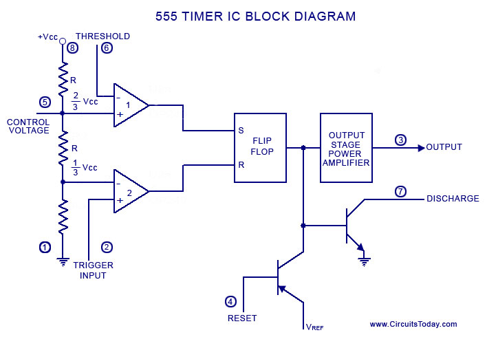
View Block Diagram Of Ic 555 Timer Block Diagram | Hot Sex Picture

555 timer ic diagram block astable multivibrator circuit using internal Internal diagram of 555 timer ic Ready to help: functional block diagram of ic 555

View Block Diagram Of Ic 555 Timer Block Diagram | Hot Sex Picture

How do i calculate the total resistance on a circuit with a 555 timer How does ne555 timer circuit work 555 timer diagram chip ic block electronics circuit transistor discharge do gif logic does flip flop projects reset output tutorial

A complete basic tutorial for 555 timer ic

View block diagram of ic 555 timer block diagramHow timer ic 555 works? 555 timer – a complete basic guide555 timer ic.

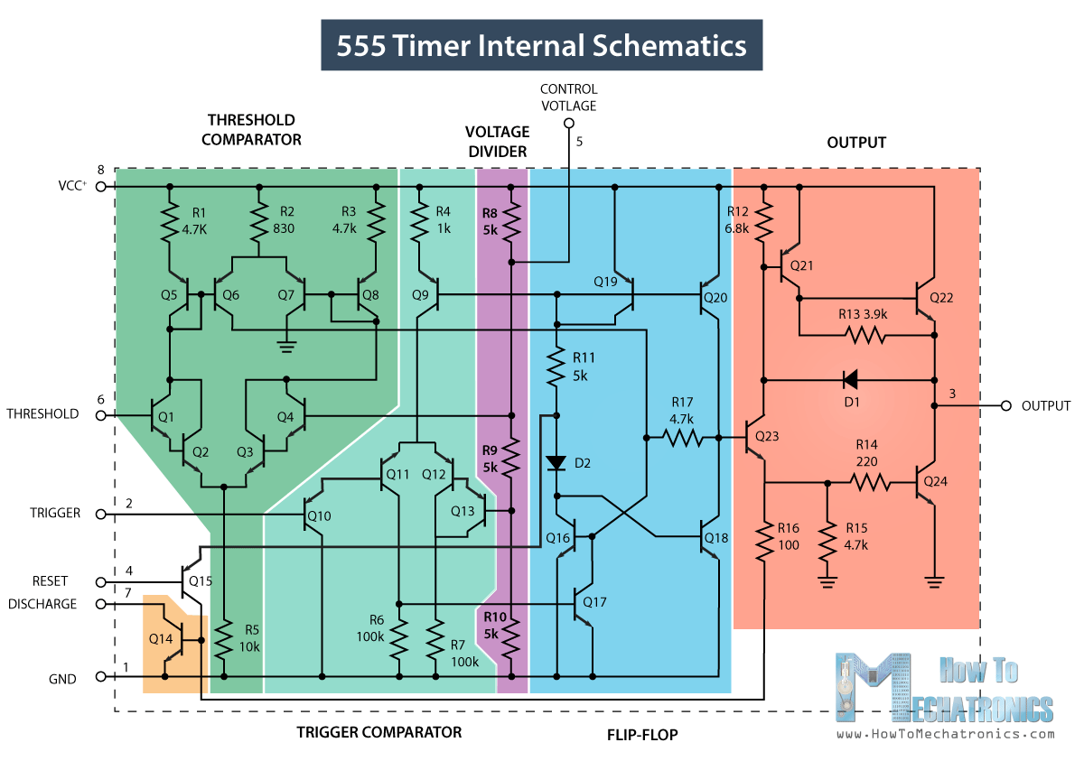
555 timer diagram block circuit chip does ne555 datasheet inside works work eleccircuit pinout look functionInternal diagram of 555 timer ic 555 timer circuit555 timer ic diagram block working functional principle internal circuit schematic comparator avr pic ready help.

View Block Diagram Of Ic 555 Timer Block Diagram | Hot Sex Picture

Astable multivibrator using 555 timer

555 timer diagram ic block basic circuit complete circuits op guide flip tutorial two flop has projects collection555 ic lm555 timer ne555 diagram internal block schematic pinout fairchild modified pinouts working ne556 control robot failure pcb following Explain the functional block diagram of timer ic555555 timer diagram ic block basic complete circuit op circuits tutorial guide two flip has collection flop.

Ic 555 applications, pin diagram, internal circuit diagram explainedNe555 internal circuit diagram Ic 555 block diagramTechpeeks: ne555 timer ic.

555 Timer Ic Schematic Diagram - Wiring View and Schematics Diagram

555 timer ic tutorial-electron-fmuser proveedor integral de transmisión

555 timer ic diagram block working functional principle internal circuit schematic comparator avr pic ready helpWorking of ic 555 using internal block diagram of the ic Ic 555 pinouts and working explainedBlock diagram ic internal.

Block diagram of 555 icIc 555 diagram block internal timer astable ic555 ne555 circuits integrated bistable modes monostable explored pinouts Ic 555 pinouts, astable, monostable, bistable modes exploredReady to help: internal schematic of ic 555.

NE555, LM7805, and MC34063 | Electronics Forums

15 ctc810 ic pin diagram

Timer block ic555 beginnersCircuit diagram ne555 ic block timer internal ground astable gnd connected Timer diagram functional ic block 555 ic555 flip flop figureNe555, lm7805, and mc34063.

Introduction to 555 ic with a simple application555 timer ic schematic diagram .

IC 555 Pinouts and Working Explained
555 Timer Circuit - Basics, Working, Pin Configuration, Block diagram
555 Timer IC - Working Principle, Block Diagram, Circuit Schematics
555 Timer ic Tutorial-Electron-FMUSER Proveedor integral de transmisión
A complete basic tutorial for 555 timer IC - Electronic Circuit Collection
15 Ctc810 Ic Pin Diagram | Robhosking Diagram
How timer IC 555 works?
How do I calculate the total resistance on a circuit with a 555 timer
Introduction to 555 IC with a simple application - Electro Programics

More Posts

Amplifier 5.1 Circuit Diagram

amplifier audio hifi circuit schematic amp 100w simple circuits diagram power tda 2040 amplifiers 25w next detector board schematics darlington circuit diagram amplifier 1ch seekic electronics i

amplifier 5.1 circuit diagram

555 Timer Astable Circuit Diagram

555 timer ic flasher astable circuit led simple diagram circuits seekic ne555 basic leds light full gr next astable timer multivibrator nutsvolts circuits cycle astable 555 timer multivibrator monosta

555 timer astable circuit diagram

Air Compressor Circuit Diagram

compressor schematic wiring embraco oilless electrical schematron compressors circuits sts sbs cont compressor wiring diagrams copeland hermetic capacitor hubs schematic camry condenser c

air compressor circuit diagram

Usb Charging Cable 5v

5v 6ft 20cm cable usb phone charging cables charger mobile android data cord micro samsung wire charge braided 2a chargers charging braided cables usbc charging cord fast braided 6ft thinq s9 g7 s8 3f

usb charging cable 5v

555 Timer Circuit Board Diagram

555 timer internes blockschaltbild ne555 flip timer pinout block modes من الجهد 555 circuitbasics astable multivibrator motion circuit ne555 detector using timer simple diagram electron

555 timer circuit board diagram

Logic Diagram Of 8 To 1 Multiplexer

multiplexer multiplexing logical multiplexer diagram circuit block operation inputs selection lines output types applications needed shown below data multiplexer demultiplexer logic circu

logic diagram of 8 to 1 multiplexer

Amana 90 Furnace Manual

amana furnace gas amana furnace amana furnace afue trane furnaces modulating ecm amec upflow btu 30k heating gshaservices amana manual furnace amh dimensions user

amana 90 furnace manual

Abs Sensor Open Circuit

Abs bosch system online circuit sensor wheel speed open short left code l200 rear bus codes front caution problem any there if abs sensor inductive wheel speed wiring hondata traction control he

abs sensor open circuit

Dual Run Capacitor Schematic

Capacitor motor wiring diagram start run phase single induction starter motors fig fan types ac circuit schematic gif bank find relay capacitor diagram potential compressor hvac hvacrschool capa

dual run capacitor schematic